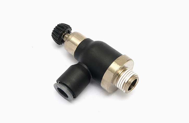
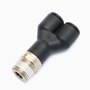
This is a Legris pneumatic connector, 7065 throttle valve. The valve body of this large flow speed regulating valve is formed in one step, and has a larger flow rate than other speed regulating connectors on the market. The air flow can be completely closed, which not only saves time but also improves production efficiency. It uses a large-diameter air intake, has ultra-high sensitivity, and can adjust the flow at will, which is handy and suitable for equipment with relatively high flow requirements.
(1) Legris pneumatic connector, 7065 throttle valve.
(2) The valve body is molded in one step, has ultra-high sensitivity, and can be fully closed.
(3) This series of throttle valves has a larger flow rate than general brand speed regulating joints, so it can help you improve production efficiency.
(4 ) Larger flow rate than general brand speed regulating joints; full flow, smaller pressure drop.
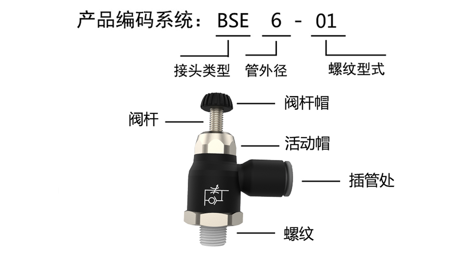
(5) With two adjustment modes, external adjustment and safety adjustment screw, it provides the characteristics of precision adjustment, accuracy and compactness
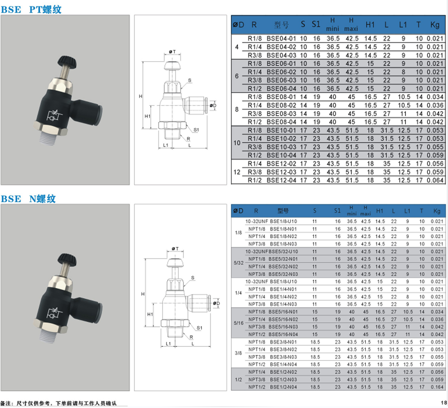
(6) Large flow control valve material: nickel-plated copper, engineering plastics, stainless steel, NBR. • Pressure: vacuum to 10 bar.
(7) Ergonomically designed, the product has a wide range of applications, is easy to adjust, does not require tools, and can be locked.