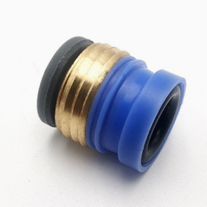
Straight-through check valve
Legris pneumatic connector – 7996 check valve. Straight-through check valve allows compressed air to flow in only one direction without reverse flow. Installed at the air inlet of the loop, it provides protection for the system. Use color codes to correctly install the check valve at the air inlet or exhaust end, so that the system will not be damaged due to installation errors, while reducing the cost caused by installation errors and making the installation process safer and more stable.
Product Contents
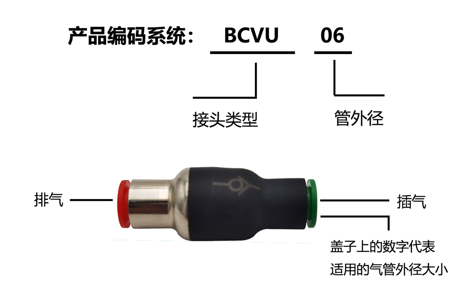
Straight-through check valve, also known as Legris pneumatic connector, allows compressed air to flow in only one direction without backflow. The circuit can be quickly designed and installed. It is installed at the air inlet end of the circuit to provide protection for the entire system. The two valves of the check valve are represented by red and green, respectively, for air inlet and exhaust, which facilitates you to correctly install them at the air inlet or exhaust end. There will be no damage to the system due to installation errors, while reducing the cost caused by installation errors and making the installation process safer and more stable. The connector has good pressure resistance, temperature resistance and fluid adaptability. Connection and disconnection can be achieved manually instantly. Straight-through check valves are used for fluids such as compressed air, natural gas or liquid.
Product Features:
(1) Legris pneumatic connector, 7996 check valve.
(2) The one-way valve allows compressed air to flow in only one direction without reverse flow. It is installed at the air inlet end of the circuit to provide protection for the system.
(3) Use color codes to ensure that the check valve is correctly installed at the intake or exhaust end, preventing system damage due to installation errors and reducing the costs caused by installation errors.
(4) Light weight, compact structure, and edge seal improves sealing performance.
Specifications:
Scope of application
Compressed air, vacuum, water
Vacuum Capacity
755mmHg (99% vacuum)
Operating temperature
0~+60℃
Work Pressure
When the working temperature is 0~10℃, it can reach 10Bar. The specific working pressure is related to the type of plastic pipe used.
Materials used
Engineering plastics, nitrile rubber, stainless steel
Model:
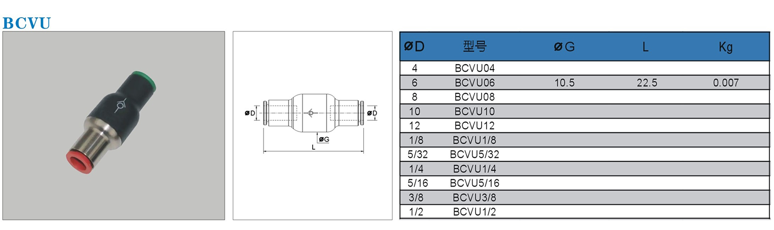
BCVU
Working temperature:
0℃/+60℃
Maximum operating pressure:
10 Bar
Material:
engineering plastics, nitrile rubber
Applicable media:
compressed air, vacuum, water
Vacuum rated pressure:
755 mmHg (99% vacuum)
Suitable for pipe outer diameter: Ø6
Precautions for using trachea pneumatic joints:
1. Make sure that the cut surface of the pipe is vertical, there are no scratches on the outer circumference of the pipe, and the pipe is not oval.
2. When inserting the pipe, be sure to insert it to the bottom of the joint. If the pipe is not inserted to the bottom, it may cause leakage.
3. After the pipes are connected, pull the pipes to make sure that the pipes cannot be pulled out of the joints.
4. Please do not use for purposes other than fluids.
5. Do not exceed the maximum operating pressure during use.
6. Do not use it outside the operating temperature range to prevent deformation of the sealing material, which may cause leakage.
7. Do not hit, bend or stretch it artificially to prevent damage.
8. Do not use in places mixed with metal powder or sand dust, as attachment of debris may cause malfunction or leakage.
Notes when disassembling:
1. Use appropriate tools to disassemble the pipe joint using the outer hexagonal part of the pipe joint.
2. Remove the sealing material adhering to the opposite side of the pipe joint to prevent the adhering sealing material from entering the surrounding components and causing failure.
2. Remove the sealing material adhering to the opposite side of the pipe joint to prevent the adhering sealing material from entering the surrounding components and causing failure.